I've talked before about new things we have learned/used,
now i'm gonna talk about the purpose of the project itself, and before i'll try to explain what's the 'Computer Architecture' about,,,
Amigos team and Wael Abu El-Kheir (Compter & Info. Sciences-Ain Shams, 3rd Year students) worked in that project, trying to make something useful for architects and students or doctors to check their designs ;)... correct design -> correct simulator results, and vice-versa :D
What's the computer architecture?
A computer contains a CPU that process all data, Memory that stores data, and other devices such as hard-disk, I/O devices...
First, the architecture deals with how that processor works, or how to make it work... how to make it understand that a given string of 0's and 1's means ADD or SUBtract or whatever?
Second, it start looking for how to manage the processor activities with other devices arrond
A written code (Assembly, C, etc...) is first Assembled/Compiled , that produces the '.obj' file containing 0's and 1's, each code instruction has it's 'opcode' (string of 0'sand 1's) that identifies it, those binaries are stored in memory then read by the processor as input to the CLU (Control Logic Unit), that unit takes input, then inside it performs a number of logical operations, and outputs to the control lines (increment, clear, load, read, write) of the desired Register, RAM, MUX, etc..
That's all about architecture.
What Archigos do ?
The idea is to make a dynamic emulator, we may call it simulator. That takes the computer architecture design description as input, then it simulates that desgin. i doubt u got what i mean :D !
ok, the design contains some wires that are inputs to some logical gates and are not output of any logical gate,,, those wires are 'pure' inputs, that means i should feed it with there values for the CLU to work
other wires are output of some logical gates, and are not input to any other gate, those are called pure output, outputs on those wires is what i need to control my computer components
I give the simulator the CLU description, give it input, connect output wires with control lines of componenets i represent as objects in my simulator, then press 'Run' it shows the effect of given input on the computer components.
I wish it's somehow clear now :D
we used Electronics Workbench to draw the CLU and to transfer it to Netlist file, we parse (.net Regex) that netlist to produce a C# code (.net CodeDOM library) , all is logical expressions
Compiling then Invoking the generated function (.net Reflection) , returns output that is connected to my objects control lines (object references -pointers do undefined behavior :( )
That's it all.
The compuer components are till now statically repreented inside the code, that's the computer components are code defined, and so connections between components
We look to make that dynamic, no more components are defined inside the code, a user then should create the component he would like to add to his computer, and its control lines will appear for matching with the design wires,,, and so entire connections between components gonna be done graphically
Some screen shots: ( you won't notice any funky interfaces :D )
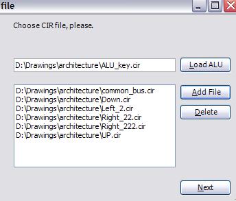
I didn't talk about ALU as i actually forgot it :D, it's that part of the computer that performs arithmetic and logical operations, it has its own parsing techniques cuz we won't draw it all, we just draw its first, and last stage , and the ith stage, that's gonna be repeated n-times
other files are the CLU design description
pressing next parses these files, and determines if there is 'resursive' connections or 'duplicate' output names (those conditions are denied).
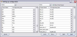 left grid is for pure input wires and right one is for outputs (an option above is available for showing non-pure outputs too)
left column of each contains wires determined in the design, right column are control lines of objects in application
I may save matching for later use, and also names that nearly look like each other are matched automatically
Pressing next, generates the C# code, and sort statements (as some output maybe input to another statement, it should be evaluated first)
any errors (all input wires should be matched, warning that maybe some control lines are not connected to any wire), the architect is notified
Then running the simulator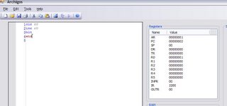 The simulator performs on the latest loaded design, the architect may move step-by-step are run the appication till a breakpoint or halted
A downloadable (source and executable) version will be available soon isA
That's it :D
And now i should run to start studying for final exams :
salaaaaam :D
ليست هناك تعليقات:
إرسال تعليق